
- High-Performance Doors
-
- Applications
-
-
-
- Clean Room
Stainless steel or composite materials help maintain clean rooms.
-
-
- Coolers
Quick opening speeds & tight seals for temperature control.
-
-
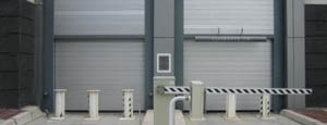
- Parking
Improve security & traffic flow and enhance architectural style.
-
-
- Hurricane Zone
Withstand winds up to 175 mph and comply with the Florida Building Code.
-
-
-
-
- USDA / FDA / cGMP
Increase productivity & address stringent USDA, FDA & cGMP requirements.
-
-
- Freezers
High-speed & perimeter seals minimize the air exchange between areas.
-
-
- Security
High speed & durability ensure secure access.
-
-
- Ventilation
Perforated or screen door panels allow improved air circulation.
-
-
-
-
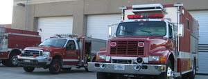
- Fire Station Emergency Response
When time is of the essence, high speed and reliability are crucial.
-
-
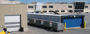
- Warehousing
Fast cycle times and secure seals keep environments separated.
-
-
- Loading Dock
Rugged design & secure seal for oversized openings.
-
-
- Large Openings
Break-away functionality with rugged design seals oversized openings.
-
-
-
-
- Heavy Equipment
Withstands challenges of heavy equipment and fleet truck/car wash environments.
-
-
- Self-Storage
Fast opening speeds and reliable, durable construction keep facilities secure and protected.
-
-
- Industries
-
-
-
- Automotive Dealerships
Reduce energy costs, increase productivity and comfort and enhance customer perception.
-
-
- Cold Storage & Processing
Increase productivity and operational efficiency while reducing energy and maintenance costs.
-
-
- Parking
We offer solutions for Apartment / Condo & Loft, Standalone Parking Facilities and Office Buildings
-
-
-
-
- Food & Beverage
Doors specifically engineered for USDA/FDA and cGMP environments, and assured compliance for uncompromising performance.
-
-
- Mfg/Dist/Warehousing
A complete product line allows facilities to increase efficiency and safety and reduce maintenance and energy costs.
-
-
- Government
Ensure effective security and environmental controls are maintained for critical government operations.
-
-
-
-
- Transit
Keep operations running smoothly and efficient while reducing energy and maintenance costs.
-
-
- Pharma, Nutraceutical & Biotech
Doors that offer quick, secure access, environmental control and reliability for life science facilities.
-
-
- Support Resources
- Parts
- Contact Us
- Blog/News
- Why Rytec
- Sales Rep Locator
- Careers
- Dealers
- Architectural Resources


















2026 Best Turbine Generator For WTE How to Choose?
Choosing the 2026 Best Turbine Generator For Wte requires more than comparing nameplate capacity. A waste-to-energy plant faces changing steam conditions, corrosive compounds, ash deposits, and demanding operating schedules. The right turbine must remain stable when municipal waste composition shifts from dry packaging to wet food residues.
Professor Nickolas J. Themelis, founder of Columbia University’s Earth Engineering Center, stated, “Waste-to-energy is a renewable energy source because waste is continually generated.” His observation supports a practical point: reliable energy recovery depends on continuous, well-controlled operation, not impressive specifications alone. A turbine generator should match the boiler’s steam pressure, temperature, flow range, and planned electrical output.
Small details matter. Check the exhaust pressure, blade material, sealing system, vibration limits, and generator cooling method. Review performance at partial load, not only at rated load. Ask suppliers for measured operating data from comparable WTE facilities. A glossy efficiency figure may hide difficult maintenance conditions.
There is no universal best choice.
Operators should also examine start-up frequency, grid connection requirements, spare-parts access, and technician support. In coastal plants, salt exposure may accelerate corrosion. In older facilities, limited space can make installation surprisingly difficult. These constraints are easy to underestimate.
A careful selection process should compare lifecycle cost, availability, service response, and emissions-control integration. Purchase price matters, but downtime costs more. Even experienced teams can misjudge future waste characteristics. That uncertainty deserves a realistic allowance. The strongest 2026 solution is not necessarily the largest turbine. It is the turbine generator that fits the plant’s actual steam profile and keeps producing safely, efficiently, and consistently.
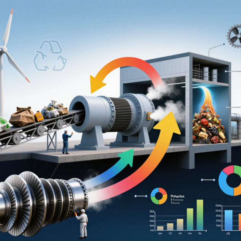
Table of Contents [Hide]
WTE Turbine Generators: Operating Principles and Main Configurations
2026 Best Turbine Generator for WTE: How to Choose?
A waste-to-energy (WTE) turbine generator converts thermal energy into electricity through a controlled steam cycle. Waste burns in a boiler, producing high-pressure steam. The steam expands through turbine stages and drives an electrical generator. Condensers then return water to the boiler. The cycle is simple in theory. Real plants are less predictable.
UNEP’s Global Waste Management Outlook 2024 estimates global municipal waste will rise from about 2.1 billion tonnes in 2023 to 3.8 billion tonnes by 2050. That growth increases demand for reliable WTE capacity. However, waste composition changes daily. Moist food waste lowers heating value, while plastics may raise furnace temperatures. Operators should examine annual steam flow, pressure stability, corrosion risk, and planned operating hours before selecting turbine output.
Three main configurations serve different sites. A condensing turbine maximizes electricity when no stable heat customer exists. A back-pressure turbine supplies useful steam or hot water, but it needs a dependable heat demand. An extraction-condensing turbine offers adjustable power and process steam. It is flexible, but mechanically more complex. The European Commission’s Waste Incineration BREF highlights corrosion control, flue-gas treatment, and energy efficiency as linked design concerns. Higher steam temperature can improve efficiency, yet it may accelerate superheater corrosion. That trade-off is often underestimated. Site data should lead the decision, not a brochure rating.
2026 Best Turbine Generator for WTE: How to Choose? — WTE Turbine Generators: Operating Principles and Main Configurations
The table below summarizes commonly used turbine-generator configurations for waste-to-energy plants. Values are typical engineering ranges rather than guaranteed performance figures; final selection requires a site-specific heat-and-mass balance, fuel analysis, steam-cycle study, and grid assessment.
| Turbine Configuration | Operating Principle | Typical Main Steam Conditions | Typical Exhaust or Extraction Condition | Best-Fit WTE Application | Main Advantages | Key Limitations and Selection Considerations |
|---|---|---|---|---|---|---|
| Condensing Steam Turbine Generator | High-pressure steam expands through multiple turbine stages to a low-pressure condenser. The condenser maintains vacuum, increasing the expansion ratio and converting more steam energy into electrical power. | Approximately 40–65 bar(a) 380–450°C | Approximately 0.05–0.15 bar(a) Saturated or slightly superheated exhaust steam | Electricity-focused WTE plants where export power is the primary energy product and there is limited demand for usable process heat. | High electrical output for a given steam flow; stable operation; suitable for grid-connected base-load generation; well-established water-steam-cycle technology. | Requires a condenser and cooling system; lower total energy utilization when no heat customer exists; cooling-water or air-cooled-condenser performance strongly affects output. |
| Extraction-Condensing Steam Turbine Generator | Steam is extracted from one or more intermediate turbine stages for district heating, process steam, deaerator service, or feedwater heating. The remaining steam continues to the condenser. | Approximately 40–65 bar(a) 380–450°C | Controlled extraction commonly about 2–20 bar(a); final exhaust typically 0.05–0.15 bar(a) | WTE plants requiring both electricity and flexible heat or steam supply, especially facilities with seasonal or variable heat demand. | Flexible balance between power production and useful heat; can supply multiple pressure levels; maintains condensing capability when heat demand falls. | More complex control and protection systems; extraction reduces electrical output; turbine design must accommodate changing extraction flow and pressure. |
| Back-Pressure Steam Turbine Generator | Steam expands through the turbine and exits at a controlled pressure above atmospheric pressure. Exhaust steam is directly used for heating or industrial processes rather than condensed for maximum power generation. | Approximately 40–65 bar(a) 380–450°C | Commonly about 2–10 bar(a), depending on the heat user | WTE facilities located near a dependable district-heating network or continuous industrial steam customer. | Simple and efficient combined heat-and-power arrangement; reduced condenser duty; high overall fuel-energy utilization when heat demand is reliable. | Electrical output depends on the required exhaust pressure; limited flexibility during low heat demand; unsuitable when there is no stable steam or heat off-taker. |
| Controlled-Extraction Back-Pressure Turbine | Steam is extracted at a controlled intermediate pressure, while the remaining steam expands to a higher-pressure back-pressure exhaust for another heat user or process stage. | Approximately 40–65 bar(a) 380–450°C | Extraction commonly about 3–15 bar(a); final exhaust commonly about 1.5–5 bar(a) | WTE sites serving two or more heat users with different pressure requirements. | Supports multi-level heat supply; can achieve high combined heat-and-power utilization; useful for integrated municipal and industrial energy systems. | Higher mechanical and control complexity; operating range must be checked carefully against minimum steam flow, heat demand, and turbine stability limits. |
| Single-Casing or Compact Small Steam Turbine | A compact turbine expands a relatively modest steam flow through a small number of stages and drives a generator directly or through a speed-reduction gearbox. | Approximately 20–45 bar(a) 300–420°C | Condensing: about 0.08–0.20 bar(a) Back-pressure: about 2–10 bar(a) | Small WTE plants, sewage-sludge incineration facilities, or sites with limited steam production and restricted installation space. | Compact footprint; lower initial equipment complexity; suitable for modest electrical capacities; simpler installation and maintenance planning. | Lower efficiency at very small scale; greater sensitivity to steam-flow changes; auxiliary power, standby requirements, and minimum-load performance should be evaluated. |
| Reheat Condensing Steam Turbine | Steam expands through a high-pressure turbine section, returns to the boiler or reheater for temperature recovery, and then expands through intermediate- and low-pressure stages. | Main steam commonly about 60–100 bar(a) 450–540°C | Typically about 0.05–0.12 bar(a) at the condenser | Large WTE plants with high steam flow, high annual operating hours, and sufficient boiler and materials capability for advanced steam conditions. | Can improve cycle efficiency and reduce moisture in the final turbine stages; appropriate for large, electricity-oriented installations. | Higher capital cost and system complexity; WTE flue-gas corrosion, high-temperature materials, boiler availability, and maintenance requirements can limit economic benefit. |
| Air-Cooled Condensing Turbine Generator | The turbine exhaust is condensed in an air-cooled condenser. Ambient air removes heat through finned tubes, eliminating the need for a large continuous cooling-water supply. | Commonly about 40–65 bar(a) 380–450°C | Approximately 0.08–0.25 bar(a), depending on ambient temperature and condenser design | Water-constrained, arid, remote, or land-based WTE sites where wet cooling is impractical or environmentally restricted. | Very low process-water consumption; reduced dependence on cooling-water infrastructure; easier siting where water availability is limited. | Higher back pressure during hot weather; larger footprint and fan power demand; electrical output can vary significantly with ambient temperature and wind conditions. |
| Water-Cooled Condensing Turbine Generator | Turbine exhaust steam is condensed using circulating cooling water in a surface condenser. Heat is rejected through a cooling tower, river, seawater system, or other approved heat sink. | Commonly about 40–65 bar(a) 380–450°C | Approximately 0.05–0.12 bar(a), subject to cooling-water temperature and condenser cleanliness | WTE plants with reliable cooling-water availability and sufficient space or permits for cooling towers and water-treatment systems. | Generally lower condensing pressure than air cooling; strong hot-weather performance; compact condenser arrangement for suitable sites. | Requires water intake, treatment, blowdown management, and corrosion control; environmental permits and water availability may be decisive. |
| Synchronous Generator Package | The steam turbine drives a synchronous generator whose rotor speed is synchronized with the grid frequency. Typical two-pole or four-pole designs operate at 3,000 or 1,500 rpm on a 50 Hz grid and 3,600 or 1,800 rpm on a 60 Hz grid. | Generator voltage commonly about 3.3–15 kV Frequency: 50 or 60 Hz | Power factor commonly designed around 0.8–0.95, depending on the grid code and excitation system | Grid-connected WTE projects requiring voltage control, fault-ride-through capability, and compliance with utility interconnection requirements. | Can provide reactive-power support; suitable for stable parallel operation; widely used for medium- and large-scale turbine-generator sets. | Requires excitation, synchronization, protection, and grid-code compliance systems; generator selection must match turbine speed, output, voltage, and short-circuit requirements. |
| Induction Generator Package | The turbine drives an asynchronous generator that obtains magnetizing current from the grid or from power-electronic equipment. It normally operates with a small slip relative to synchronous speed. | Commonly used for smaller output ranges Voltage and frequency selected for the local grid | Typically requires grid support for reactive power unless capacitor banks or converters are installed | Small, stable-output WTE applications with a strong grid connection and limited requirements for independent voltage regulation. | Simple construction; generally robust; potentially lower package complexity for small units. | Limited reactive-power and islanding capability; less suitable for weak grids, independent operation, or applications requiring precise voltage control. |
| Modular Multi-Unit Turbine-Generator System | Several smaller turbine-generator sets operate in parallel. Units can be started, stopped, or operated at different loads to match changing steam production from multiple waste-processing lines. | Each unit is designed for its own steam flow and pressure Common WTE steam conditions remain project-specific | Condensing, extraction, or back-pressure operation can be arranged by module | Plants with multiple incinerator lines, fluctuating waste throughput, staged expansion, or a strong requirement for partial-load availability. | Better redundancy; flexible maintenance scheduling; improved matching of turbine capacity to changing steam flow; easier phased capacity expansion. | More balance-of-plant equipment, controls, valves, and maintenance points; total cost per kilowatt can be higher than a single optimized unit. |
Key selection criteria: Evaluate waste composition and lower heating value, annual steam-flow profile, main-steam pressure and temperature, corrosion and erosion risk, required electricity-to-heat ratio, cooling-water availability, grid conditions, expected operating hours, minimum stable load, plant availability target, maintenance strategy, and the value of exported electricity and useful heat. In WTE service, reliable long-term operation and corrosion-resistant boiler and turbine-cycle design are often more important than maximizing the nameplate electrical efficiency alone.