
- High-Performance Doors
-
- Applications
-
-
-
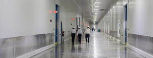
- Clean Room
Stainless steel or composite materials help maintain clean rooms.
-
-
- Coolers
Quick opening speeds & tight seals for temperature control.
-
-
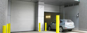
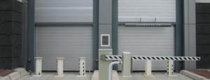
- Parking
Improve security & traffic flow and enhance architectural style.
-
-
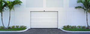
- Hurricane Zone
Withstand winds up to 175 mph and comply with the Florida Building Code.
-
-
-
-
- USDA / FDA / cGMP
Increase productivity & address stringent USDA, FDA & cGMP requirements.
-
-
- Freezers
High-speed & perimeter seals minimize the air exchange between areas.
-
-
- Security
High speed & durability ensure secure access.
-
-
- Ventilation
Perforated or screen door panels allow improved air circulation.
-
-
-
-
- Fire Station Emergency Response
When time is of the essence, high speed and reliability are crucial.
-
-
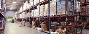
- Warehousing
Fast cycle times and secure seals keep environments separated.
-
-
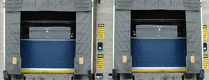
- Loading Dock
Rugged design & secure seal for oversized openings.
-
-
- Large Openings
Break-away functionality with rugged design seals oversized openings.
-
-
-
-
- Heavy Equipment
Withstands challenges of heavy equipment and fleet truck/car wash environments.
-
-
- Self-Storage
Fast opening speeds and reliable, durable construction keep facilities secure and protected.
-
-
- Industries
-
-
-
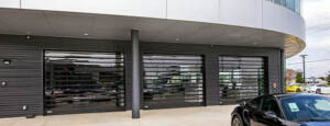
- Automotive Dealerships
Reduce energy costs, increase productivity and comfort and enhance customer perception.
-
-
- Cold Storage & Processing
Increase productivity and operational efficiency while reducing energy and maintenance costs.
-
-
- Parking
We offer solutions for Apartment / Condo & Loft, Standalone Parking Facilities and Office Buildings
-
-
-
-
- Food & Beverage
Doors specifically engineered for USDA/FDA and cGMP environments, and assured compliance for uncompromising performance.
-
-
- Mfg/Dist/Warehousing
A complete product line allows facilities to increase efficiency and safety and reduce maintenance and energy costs.
-
-
- Government
Ensure effective security and environmental controls are maintained for critical government operations.
-
-
-
-
- Transit
Keep operations running smoothly and efficient while reducing energy and maintenance costs.
-
-
- Pharma, Nutraceutical & Biotech
Doors that offer quick, secure access, environmental control and reliability for life science facilities.
-
-
- Support Resources
- Parts
- Contact Us
- Blog/News
- Why Rytec
- Sales Rep Locator
- Careers
- Dealers
- Architectural Resources













How to Choose Marine Steel Pipes for Global Projects?
Marine Steel Pipes support seawater intake systems, ballast lines, offshore platforms, and port infrastructure. Their selection affects safety, maintenance costs, and project continuity. The maritime environment is unforgiving. Salt spray reaches exposed surfaces, while currents create repeated stress around joints and supports.
Industry data explains the scale of this decision. UNCTAD’s Review of Maritime Transport 2024 reports that more than 80% of global merchandise trade moves by sea. The World Steel Association also records global crude steel production near 1.9 billion tonnes annually. These figures show why reliable steel supply and consistent quality matter across international projects. A pipe chosen only by diameter or price may create serious problems later.
The right specification should consider strength, wall thickness, corrosion allowance, weldability, coating compatibility, and inspection requirements. DNV and ISO standards provide useful technical frameworks for offshore and marine applications. API 5L may support pipeline requirements, while EN 10225 addresses offshore structural steel grades. However, standards do not replace engineering judgment. Actual seawater chemistry, design temperature, loading cycles, and installation conditions must be reviewed.
No single grade fits every project. That assumption can fail.
Experienced buyers should verify mill certificates, heat numbers, third-party inspection records, and traceability documents. They should also examine delivery routes, storage conditions, and repair procedures at the destination port. A polished specification can still hide a weak assumption. For this reason, choosing Marine Steel Pipes requires cooperation among designers, fabricators, inspectors, and logistics teams. The most reliable decision balances technical performance, documented compliance, lifecycle cost, and practical site experience.
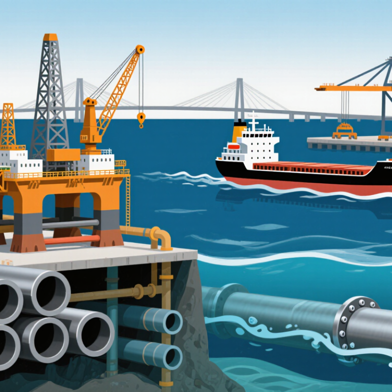
Table of Contents [Hide]
Classify Service Conditions: 3.2% Seawater, Pressure, Temperature, and Depth
How to Choose Marine Steel Pipes for Global Projects?
Marine projects begin with service conditions, not a catalog diameter. Define whether the pipe carries 3.2% seawater, treated water, or another medium. Salinity changes with location, so confirm the actual chemistry, oxygen level, and flow speed. These details influence corrosion allowance, coating selection, and inspection frequency. A pipe exposed to seawater may require stronger corrosion protection than one carrying fresh water. Do not treat 3.2% as a universal constant.
Pressure also changes sharply with depth. Hydrostatic pressure rises by roughly 0.1 MPa for every ten metres of seawater. External pressure can collapse a thin-wall pipe, even when internal pressure is low. Check wall thickness, ovality, stiffeners, and buckling resistance together. Temperature affects yield strength, toughness, and welding behavior. Cold seabed conditions can expose weak impact performance. The first calculation is rarely the final one.
Tips: Build a service-condition sheet before requesting quotations. Record salinity, pressure, depth, temperature range, flow rate, and design life. Ask for heat numbers, test records, weld procedures, and non-destructive examination results. Verify the design with an independent engineer. Small gaps in data can become expensive assumptions.