
- High-Performance Doors
-
- Applications
-
-
-
- Clean Room
Stainless steel or composite materials help maintain clean rooms.
-
-
- Coolers
Quick opening speeds & tight seals for temperature control.
-
-
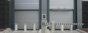
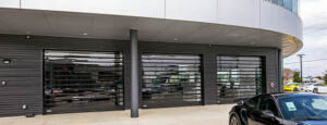
- Parking
Improve security & traffic flow and enhance architectural style.
-
-
- Hurricane Zone
Withstand winds up to 175 mph and comply with the Florida Building Code.
-
-
-
-
- USDA / FDA / cGMP
Increase productivity & address stringent USDA, FDA & cGMP requirements.
-
-
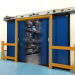
- Freezers
High-speed & perimeter seals minimize the air exchange between areas.
-
-
- Security
High speed & durability ensure secure access.
-
-
- Ventilation
Perforated or screen door panels allow improved air circulation.
-
-
-
-
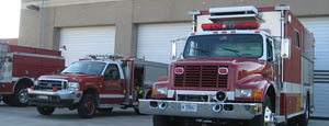
- Fire Station Emergency Response
When time is of the essence, high speed and reliability are crucial.
-
-
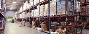
- Warehousing
Fast cycle times and secure seals keep environments separated.
-
-
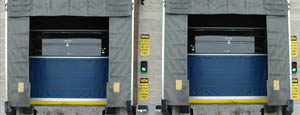
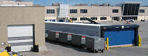
- Loading Dock
Rugged design & secure seal for oversized openings.
-
-
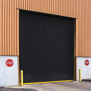
- Large Openings
Break-away functionality with rugged design seals oversized openings.
-
-
-
-
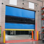
- Heavy Equipment
Withstands challenges of heavy equipment and fleet truck/car wash environments.
-
-
- Self-Storage
Fast opening speeds and reliable, durable construction keep facilities secure and protected.
-
-
- Industries
-
-
-
- Automotive Dealerships
Reduce energy costs, increase productivity and comfort and enhance customer perception.
-
-
- Cold Storage & Processing
Increase productivity and operational efficiency while reducing energy and maintenance costs.
-
-
- Parking
We offer solutions for Apartment / Condo & Loft, Standalone Parking Facilities and Office Buildings
-
-
-
-
- Food & Beverage
Doors specifically engineered for USDA/FDA and cGMP environments, and assured compliance for uncompromising performance.
-
-
- Mfg/Dist/Warehousing
A complete product line allows facilities to increase efficiency and safety and reduce maintenance and energy costs.
-
-
- Government
Ensure effective security and environmental controls are maintained for critical government operations.
-
-
-
-
- Transit
Keep operations running smoothly and efficient while reducing energy and maintenance costs.
-
-
- Pharma, Nutraceutical & Biotech
Doors that offer quick, secure access, environmental control and reliability for life science facilities.
-
-
- Support Resources
- Parts
- Contact Us
- Blog/News
- Why Rytec
- Sales Rep Locator
- Careers
- Dealers
- Architectural Resources
















How to Choose the Best RO Plant Water Chiller?
Choosing the right Ro Plant Water Chiller can determine whether a reverse osmosis system runs steadily or struggles under changing production demands. In real facilities, water temperature affects membrane performance, flow consistency, energy use, and product quality. A chiller that appears suitable on paper may fail during summer operation, when feedwater enters warmer than expected. Careful selection begins with actual operating data, not only catalog capacity.
Engineers should examine cooling capacity, temperature range, flow rate, refrigerant type, materials, controls, and service access. Stainless steel wetted parts can support cleaner operation in demanding environments. Automatic temperature control helps maintain stable conditions near the membrane inlet. However, oversized equipment may waste energy and cycle inefficiently. Undersized equipment may run continuously without reaching the required temperature. Neither option is ideal.
Experience with similar RO systems offers valuable guidance. Ask suppliers for performance data at your real inlet temperature and flow conditions. Check whether the unit supports continuous duty, alarm protection, and easy filter cleaning. Independent testing, recognized quality systems, and documented maintenance procedures can strengthen confidence. Yet specifications are not everything. Site ventilation, ambient temperature, electrical supply, and operator training also influence results. Small omissions can become expensive problems.
A practical decision should balance reliability, efficiency, hygiene, installation space, and long-term support. Some recommendations may need revision after pilot testing. That is acceptable. A measured choice is safer than a confident guess.
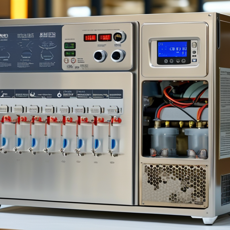
Table of Contents [Hide]
Define RO Plant Chilling Requirements and Operating Conditions
Choosing the best RO plant water chiller starts with defining the real chilling requirement, not selecting equipment from a catalog. Record feed-water flow, inlet temperature, target temperature, ambient temperature, operating hours, and seasonal variation. A plant processing 20 m³/h, cooled by 5°C, needs approximately 116 kW of heat removal, using water’s specific heat of 4.18 kJ/kg·K, as referenced in the ASHRAE Handbook. Add heat from pumps, nearby machinery, and poorly insulated pipes.
Measure the process continuously. Do not rely on one morning reading. The International Energy Agency’s The Future of Cooling report states that global cooling energy demand could more than triple by 2050, highlighting the importance of efficient, correctly sized systems. For RO operation, confirm membrane manufacturer limits, feed-water pressure, recovery rate, cleaning cycles, and acceptable temperature changes. Warmer water usually increases membrane permeability, but it can also alter salt passage and product quality.
Small details matter. A 2°C error can affect capacity calculations. Fouling adds resistance. Ambient heat can be underestimated. Use peak summer conditions, not average weather, when selecting the chiller. A practical design often includes operating margin, but excessive oversizing may cause short cycling, unstable outlet temperature, and unnecessary energy use. The U.S. Department of Energy recommends evaluating cooling-system performance under actual load conditions. A neat spreadsheet can still be wrong. Verify it against logged plant data.
How to Choose the Best RO Plant Water Chiller? - Define RO Plant Chilling Requirements and Operating Conditions
Reference design parameters for selecting and sizing a water chiller for a reverse osmosis plant. Final values should be confirmed through site measurements, water analysis, membrane design data, and a detailed heat-load calculation.
| Design Dimension | Typical Reference Value | Recommended Design Basis | Why It Matters for Chiller Selection | Verification Method |
|---|---|---|---|---|
| RO Feed-Water Flow | 1–100 m³/h for small to medium industrial RO systems | Use the maximum continuous flow, not only the average daily flow. | The flow rate directly determines the amount of water that must be cooled and affects evaporator, pump, piping, and control-valve sizing. | Confirm the rated feed-flow range from the RO system design and verify it with a calibrated flow meter. |
| Inlet Water Temperature | Approximately 15–35 °C, depending on climate, source water, and process conditions | Size the chiller for the highest expected inlet temperature during the hottest operating period. | Higher inlet temperatures increase the cooling load and can reduce RO membrane performance if the process temperature is not controlled. | Record temperature continuously for at least one representative operating period, including the seasonal high. |
| Target Process-Water Temperature | Commonly 20–25 °C for controlled RO feed-water operation | Use the membrane manufacturer’s approved operating-temperature range as the governing limit. | Temperature influences water viscosity, permeate flow, salt passage, and the pressure required to achieve the target production rate. | Review membrane design software results, operating manuals, and historical product-water quality data. |
| Required Water Temperature Reduction | Typically 3–15 K, depending on the source-water temperature and target temperature | Calculate the maximum temperature drop from the hottest inlet condition to the required outlet condition. | A larger temperature reduction produces a higher refrigeration load and may require a larger compressor, condenser, and heat exchanger. | Use the measured inlet temperature and the specified outlet temperature under peak production conditions. |
| Cooling-Duty Calculation | Cooling load (kW) ≈ 1.163 × flow (m³/h) × ΔT (K) | Add the heat load from pumps, motors, piping, tanks, and the surrounding environment. | This provides a practical first estimate for water cooling. It is based on the specific heat and density of water near normal process temperatures. | Calculate the duty at maximum flow and maximum inlet temperature, then validate it with a thermal-load assessment. |
| Example Cooling Load | For 20 m³/h cooled by 8 K: approximately 186 kW | 1.163 × 20 × 8 = 186.1 kW | The example represents sensible cooling of water only; actual chiller capacity must also include system heat gains. | Recalculate using actual plant flow, measured temperature difference, and confirmed operating hours. |
| Design Capacity Margin | Typically 10–20% above the calculated peak cooling load | Use the lower end where operating data is reliable and the upper end where conditions are variable. | A reasonable margin helps the chiller handle fouling, seasonal temperature changes, gradual performance degradation, and short-term load fluctuations. | Document the calculation assumptions and avoid excessive oversizing, which can cause short cycling and poor humidity control. |
| Chilled-Water Supply Temperature | Commonly 7–12 °C for a secondary chilled-water loop | Select the highest supply temperature that still allows the required process-water outlet temperature. | A higher chilled-water supply temperature can improve chiller efficiency, while a lower temperature may be required for a compact heat exchanger or difficult heat load. | Confirm the required approach temperature of the process heat exchanger and the minimum allowable process temperature. |
| Chilled-Water Return Temperature | Often 12–17 °C when designed for a 5 K temperature rise | Define supply and return temperatures together with the required secondary-loop flow. | The temperature difference affects chilled-water flow, pump energy, pipe size, and the required evaporator capacity. | Verify the heat exchanger design and measure supply and return temperatures during peak load. |
| Heat-Exchanger Approach Temperature | Commonly 2–5 K for a properly selected liquid-to-liquid heat exchanger | Use the exchanger supplier’s certified performance data at the actual flow rates and fouling allowance. | A smaller approach temperature generally requires more heat-transfer surface and can increase equipment cost, but it may reduce the required chiller temperature. | Check the exchanger duty, pressure drop, material compatibility, and cleanability requirements. |
| RO Feed-Water Pressure | Often 10–25 bar for brackish-water RO; seawater RO is typically much higher | Use the actual pump discharge pressure and allow for pressure losses through the cooling circuit. | The chiller is normally connected through a heat exchanger or separate loop. Pressure rating and pump selection must match the RO process. | Review the pump curve, piping layout, design pressure, relief-protection requirements, and operating transients. |
| Water Quality and Fouling Risk | Depends on hardness, alkalinity, suspended solids, iron, silica, and biological activity | Use pretreatment and filtration suitable for the selected heat exchanger and the RO feed-water quality. | Scaling and fouling reduce heat transfer, increase pressure drop, and can cause unstable outlet temperatures. | Use a current laboratory water analysis and establish cleaning frequency, filtration level, and chemical-treatment requirements. |
| Heat-Exchanger Material | Common choices include titanium, 316 stainless steel, or other corrosion-resistant materials | Select materials based on chloride concentration, pH, temperature, cleaning chemicals, and design pressure. | Material compatibility is critical because concentrated or chemically treated water can accelerate corrosion and shorten equipment life. | Compare the water analysis with material-resistance data and obtain written confirmation from the equipment designer. |
| Ambient Design Temperature | Usually 35–45 °C for outdoor installations, depending on local climate | Use the site’s recorded design summer temperature rather than a generic average. | Air-cooled chillers lose capacity and efficiency as ambient temperature rises, which may require a larger condenser or a water-cooled configuration. | Check local weather design data and evaluate condenser performance at the peak ambient condition. |
| Cooling Method | Air-cooled or water-cooled chiller | Choose according to water availability, ambient conditions, maintenance capability, noise limits, and energy objectives. | Air-cooled units are simpler where cooling water is limited; water-cooled units can be more efficient but require a cooling tower or another heat-rejection system. | Compare total lifecycle cost, water consumption, available space, seasonal performance, and maintenance requirements. |
| Control Accuracy | Typically ±1 °C for a stable process-water temperature loop | Use a modulating capacity-control system, variable-speed pump, or three-way control valve where the process load varies significantly. | Stable temperature control helps maintain consistent permeate production and reduces unnecessary compressor cycling. | Define the acceptable temperature band, sensor location, response time, and alarm limits in the control philosophy. |
| Operating Schedule | Continuous, batch, or variable-shift operation | Size for peak duty and evaluate turndown for the minimum expected load. | A chiller that is too large for low-load operation may cycle frequently, while insufficient turndown can cause temperature fluctuations and excess energy use. | Review production schedules, start-up sequences, shutdown periods, and expected daily and seasonal load profiles. |
| Energy-Use Review | Compare cooling capacity, input power, and seasonal efficiency at actual operating conditions | Evaluate performance at full load and part load, not only at the nominal rating point. | Compressor efficiency, condenser temperature, pump power, and control strategy strongly influence the total operating cost. | Request certified performance data and calculate annual energy use from the site’s operating hours and load profile. |
| System Protection | Flow switch, high/low pressure protection, freeze protection, temperature alarms, and overload protection | Interlock the chiller with the RO feed pump and stop the system when minimum flow or safe temperature limits are not met. | Protection devices prevent evaporator freezing, pump damage, loss of cooling, and operation outside the RO process limits. | Review the cause-and-effect diagram, alarm set points, emergency-stop logic, and restart sequence. |
Engineering note: The reference ranges in this table are general industrial design guidelines, not universal operating limits. The final chiller selection should be based on the actual RO membrane specification, peak water temperature, maximum flow, water chemistry, heat-exchanger design, ambient conditions, and required control accuracy.