
- High-Performance Doors
-
- Applications
-
-
-
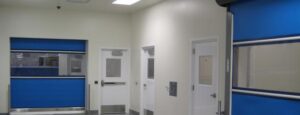
- Clean Room
Stainless steel or composite materials help maintain clean rooms.
-
-
- Coolers
Quick opening speeds & tight seals for temperature control.
-
-
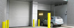
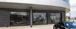
- Parking
Improve security & traffic flow and enhance architectural style.
-
-
- Hurricane Zone
Withstand winds up to 175 mph and comply with the Florida Building Code.
-
-
-
-
- USDA / FDA / cGMP
Increase productivity & address stringent USDA, FDA & cGMP requirements.
-
-
- Freezers
High-speed & perimeter seals minimize the air exchange between areas.
-
-
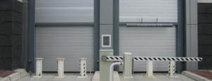
- Security
High speed & durability ensure secure access.
-
-
- Ventilation
Perforated or screen door panels allow improved air circulation.
-
-
-
-
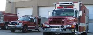
- Fire Station Emergency Response
When time is of the essence, high speed and reliability are crucial.
-
-
- Warehousing
Fast cycle times and secure seals keep environments separated.
-
-
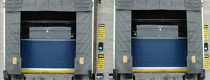
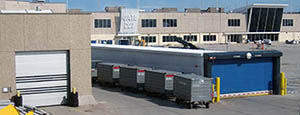
- Loading Dock
Rugged design & secure seal for oversized openings.
-
-
- Large Openings
Break-away functionality with rugged design seals oversized openings.
-
-
-
-
- Heavy Equipment
Withstands challenges of heavy equipment and fleet truck/car wash environments.
-
-
- Self-Storage
Fast opening speeds and reliable, durable construction keep facilities secure and protected.
-
-
- Industries
-
-
-
- Automotive Dealerships
Reduce energy costs, increase productivity and comfort and enhance customer perception.
-
-
- Cold Storage & Processing
Increase productivity and operational efficiency while reducing energy and maintenance costs.
-
-
- Parking
We offer solutions for Apartment / Condo & Loft, Standalone Parking Facilities and Office Buildings
-
-
-
-
- Food & Beverage
Doors specifically engineered for USDA/FDA and cGMP environments, and assured compliance for uncompromising performance.
-
-
- Mfg/Dist/Warehousing
A complete product line allows facilities to increase efficiency and safety and reduce maintenance and energy costs.
-
-
- Government
Ensure effective security and environmental controls are maintained for critical government operations.
-
-
-
-
- Transit
Keep operations running smoothly and efficient while reducing energy and maintenance costs.
-
-
- Pharma, Nutraceutical & Biotech
Doors that offer quick, secure access, environmental control and reliability for life science facilities.
-
-
- Support Resources
- Parts
- Contact Us
- Blog/News
- Why Rytec
- Sales Rep Locator
- Careers
- Dealers
- Architectural Resources















10 Tips to Choose the Right Jacquard Driving Board?
Choosing the right Jacquard Driving Board can determine whether a textile line runs smoothly or loses hours to unstable patterns and repeated adjustments. In practice, the board is not merely a control component. It coordinates electronic signals, needle selection, pattern accuracy, response speed, and communication with the loom system. A small mismatch may appear as broken motifs, uneven fabric, or unexplained machine stops.
Industry data supports careful selection. The International Textile Machinery Federation’s International Textile Machinery Shipment Statistics reports continued investment in modern weaving equipment, although demand differs across regions and machine categories. This shift increases the need for compatible, serviceable control hardware. Market reports from MarketsandMarkets also identify automation, digital control, and production efficiency as important directions in textile machinery. These reports offer useful context, but they do not replace testing the board on your actual loom.
Details matter. Check interface compatibility, output capacity, operating voltage, heat resistance, firmware support, and repair access. Ask how the board performs during long production runs, not only during a short demonstration. A supplier should provide wiring diagrams, test records, failure guidance, and traceable specifications. That evidence builds confidence.
Some choices still remain difficult. The cheapest board may reduce the purchase budget but increase downtime later. A high-end model may offer features your factory never uses. This guide presents ten practical tips for comparing a Jacquard Driving Board by reliability, integration, maintenance, and lifecycle value. Think beyond the first quotation. A stable signal at 2 a.m. can matter more than a polished sales brochure.
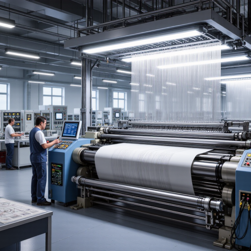
Table of Contents [Hide]
Understand Jacquard Driving Board Types and Core Functions
A Jacquard driving board controls how pattern data reaches the lifting mechanism. Its core work includes signal processing, actuator control, timing, and fault monitoring. Common types include electronic boards, modular boards, and servo-controlled boards. Electronic boards suit modern looms with digital pattern files. Modular designs help technicians replace one section without changing the entire system. Servo-controlled versions offer accurate movement and smoother speed adjustment, especially in complex patterns.
Tip 1: Match the board with the loom’s voltage, connector layout, and communication protocol. A perfect-looking board can still fail when timing signals differ.
Tip 2: Check driving capacity, including channel quantity, switching frequency, and heat tolerance. During factory testing, I inspect wiring temperature after long operation. Small heat marks often reveal overloaded circuits earlier than software alarms.
Core functions should include stable pulse output, synchronized shedding control, and protection against overcurrent or signal loss. Look for clear diagnostic indicators and accessible testing points. These details reduce downtime and make maintenance less dependent on guesswork.
Tip 3: Ask for waveform data, service records, and compatibility instructions before purchase. Technical documents are more useful than confident promises.
Tip 4: Consider future pattern expansion, not only today’s production needs. I once focused too much on initial cost; the limited interface later created unnecessary delays. A reliable choice balances response speed, repair access, operating conditions, and verified machine compatibility.