
- High-Performance Doors
-
- Applications
-
-
-
- Clean Room
Stainless steel or composite materials help maintain clean rooms.
-
-
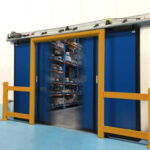
- Coolers
Quick opening speeds & tight seals for temperature control.
-
-
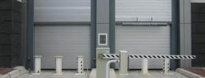
- Parking
Improve security & traffic flow and enhance architectural style.
-
-
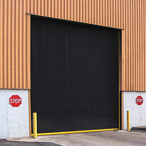
- Hurricane Zone
Withstand winds up to 175 mph and comply with the Florida Building Code.
-
-
-
-
- USDA / FDA / cGMP
Increase productivity & address stringent USDA, FDA & cGMP requirements.
-
-
- Freezers
High-speed & perimeter seals minimize the air exchange between areas.
-
-
- Security
High speed & durability ensure secure access.
-
-
- Ventilation
Perforated or screen door panels allow improved air circulation.
-
-
-
-
- Fire Station Emergency Response
When time is of the essence, high speed and reliability are crucial.
-
-
- Warehousing
Fast cycle times and secure seals keep environments separated.
-
-
- Loading Dock
Rugged design & secure seal for oversized openings.
-
-
- Large Openings
Break-away functionality with rugged design seals oversized openings.
-
-
-
-
- Heavy Equipment
Withstands challenges of heavy equipment and fleet truck/car wash environments.
-
-
- Self-Storage
Fast opening speeds and reliable, durable construction keep facilities secure and protected.
-
-
- Industries
-
-
-
- Automotive Dealerships
Reduce energy costs, increase productivity and comfort and enhance customer perception.
-
-
- Cold Storage & Processing
Increase productivity and operational efficiency while reducing energy and maintenance costs.
-
-
- Parking
We offer solutions for Apartment / Condo & Loft, Standalone Parking Facilities and Office Buildings
-
-
-
-
- Food & Beverage
Doors specifically engineered for USDA/FDA and cGMP environments, and assured compliance for uncompromising performance.
-
-
- Mfg/Dist/Warehousing
A complete product line allows facilities to increase efficiency and safety and reduce maintenance and energy costs.
-
-
- Government
Ensure effective security and environmental controls are maintained for critical government operations.
-
-
-
-
- Transit
Keep operations running smoothly and efficient while reducing energy and maintenance costs.
-
-
- Pharma, Nutraceutical & Biotech
Doors that offer quick, secure access, environmental control and reliability for life science facilities.
-
-
- Support Resources
- Parts
- Contact Us
- Blog/News
- Why Rytec
- Sales Rep Locator
- Careers
- Dealers
- Architectural Resources





















10 Tips for Choosing Hydraulic Cylinder Seals?
Choosing Hydraulic Cylinder Seals is a practical decision, not a simple catalog search. A cylinder working beside a steel press may face heat, pressure spikes, dust, and constant movement. Its seal must handle those conditions without causing leakage or premature wear. Small details matter.
This guide explains ten useful tips for selecting seals with greater confidence. It considers rod diameter, bore size, pressure, temperature, fluid compatibility, speed, and installation space. Measurements should come from the actual cylinder, not memory or an old drawing. Measure twice. A neat-looking seal can still be the wrong seal.
Material selection also deserves careful attention. Polyurethane may suit many demanding applications, while PTFE can perform well under specific temperature and friction conditions. Rubber compounds vary significantly, even when their names sound familiar. Always check the manufacturer’s technical data and operating limits. That assumption can be wrong. Seal performance also depends on the rod surface, groove condition, contamination control, and correct installation technique. A sharp groove edge can damage a new seal before the machine completes one cycle. Maintenance records can reveal patterns that product brochures cannot, such as leakage after cold starts or swelling after fluid changes. These ten tips connect those practical observations with dependable engineering principles. They are not a substitute for professional verification, but they can prevent rushed choices, costly downtime, and repeated repairs. Reliable selection begins with honest questions about the working environment.
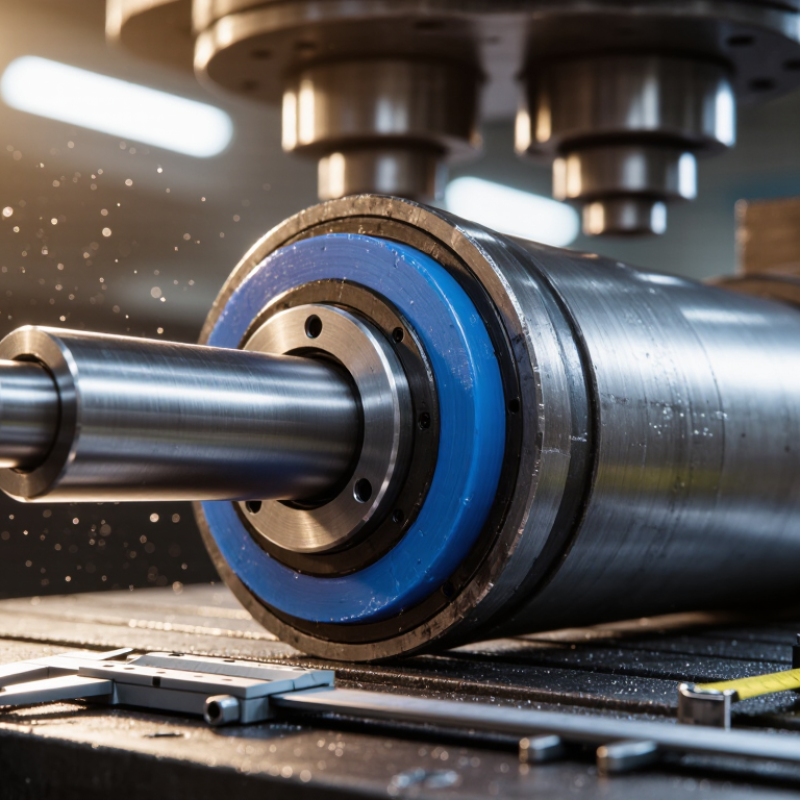
Table of Contents [Hide]
Hydraulic Cylinder Seal Functions and Operating Requirements
10 Tips for Choosing Hydraulic Cylinder Seals
Hydraulic Cylinder Seal Functions and Operating Requirements
Tip 1: Start with the seal’s job. Rod seals retain pressurized fluid, while wipers block dust, water, and metal particles. Guide rings stabilize the rod and reduce uneven loading. Tip 2: Match the seal to the fluid. Mineral oil, water-based fluids, and biodegradable fluids can affect materials differently. Tip 3: Check pressure and extrusion risk. A narrow clearance may require a stronger support ring. Small gaps can cause serious damage.
Tip 4: Record operating temperature, including short heat spikes. Tip 5: Confirm rod speed and movement frequency. High-speed cycles create heat through friction. Tip 6: Examine the rod surface closely. Scratches, corrosion, or sharp edges can cut a new seal quickly. Tip 7: Select the correct seal profile for the groove. A loose fit may leak, but excessive compression can increase drag. In field maintenance, I have seen technicians blame the seal before checking alignment. That mistake is easy to repeat.
Tip 8: Consider contamination levels around the cylinder. Tip 9: Follow clean installation practices and use suitable tools. Avoid twisting the seal during fitting. Tip 10: Review service life under real loads, not only catalog figures. Pressure surges, side loading, and poor lubrication can change performance. I would also inspect failed seals before replacing them. Sometimes the first choice was acceptable; the operating conditions were not.